

Analysing efficiency of IPv6 packet transmission
over 6LoWPAN network
autorzy:
Adam Kozłowskia, Janusz Sosnowskia
(aInstitute of Computer Science, Warsaw University of Technology, ul. Nowowiejska 15/18, Warsaw 00-665, Poland)
Abstract
Practical proliferation of Internet of Things (IoT) concept depends upon communication efficiency in the related network. In the paper we outline basic features of wireless communication protocols used in IoT and concentrate on analysing communication overheads. In particular, we discuss the impact of IPv6 packet length on 6LoWPAN network operation with physical and MAC layer defined by IEEE 802.15.4 standard. The presented analysis methodology is useful in estimation of the total goodput (throughput at the application level) and energy consumptions within the whole traffic model which are the crucial features of IoT networks.
Keywords
Personal area network, IoT, transmission overhead, 6LoWPAN, IEEE 802.15.4
1.Introduction
The Internet of things (IoT) concept covers several areas such as: communication, embedded computing, cloud computing and others. There are plenty of definitions of the IoT1 but in most of them we can distinguish the main idea which is network of uniquely identifiable physical objects interoperating within the existing Internet infrastructure. According to this definition we can find IP protocol suite to be inherent in the IoT concept. There are prognoses that the IoT will consist of more than 7 trillion objects by 20252, with an estimate of about 1000 devices per person. IPv6 protocol has enough address space to meet even further proliferation hence it is a reasonable and natural choice for the IoT. The use of an end-to-end, IP-based infrastructure takes full advantage of 40+ years of IP technology development. Wireless communication is another intrinsic feature of the IoT paradigm. There are many groups of physical objects where wireless transmission is the only feasible solution. The IEEE 802 Standard Committee develops and maintains networking standards and recommended practices. Standards for connecting physical objects with limited computing or memory resources and working without external energy for years play a special role in the development of the IoT. In particular, IEEE 802.15.4 standard3 addressed for low-cost and low-bandwidth connections provides the capability of energy consumption reduction. The use of IP protocol in low-power, wireless personal area networks (LoWPANs) was not considered for a long time because these networks are highly constrained and must operate unattended on batteries for years. Additionally, IPv6 increases the smallest (within transmission paths) maximum transmission unit (MTU) from 576 B to 1280 B. The payload of the physical frame in the IEEE 802.15.4 can be up to 127 bytes in size, with 72‑116 bytes of payload available after link-layer framing, depending on the number of addressing and security options.
6LoWPAN4 is an IETF protocol that allows IPv6 packets to be carried efficiently within small link layer frames, such as those defined by IEEE 802.15.4. The 6LoWPAN introduces an adaptation layer between the IP stack’s link and network layers to enable transmission of IPv6 packets. Transmission of IPv6 packets within small frame (PHY payload – 127 B) leads to significant transmission overhead. The length of a payload at higher layers is relatively short compared to the length of the frame. Overhead that comes from all the layers of stack has meaningful influence on total energy consumption within the entire network. It can be assumed that the energy consumption in a transmission is directly proportional to the number of sent symbols (bytes). Therefore, it is important to maximize the goodput so that less energy is consumed by all the redundant elements e.g. headers, control packets, beacons, etc.
It is crucial to assess the transmission overhead to effectively design and build 6LoWPAN networks. In the paper we analyse the overhead basing on different sets of stack options. There are some options which have meaningful impact and have to be used reasonably, they are discussed in section 2. Section 3 introduces an original model that allows determining the overhead on each layer of the stack. The mean transmission overhead of the 6LoWPAN stack was derived based on different probability distributions of the packet length within the Internet. The results are presented in section 4 followed by conclusions in section 5.
2. The 6LoWPAN stack characterisation
The 6LoWPAN protocol allows for efficient transmission of IPv6 packets over IEEE 802.15.4 networks. The stack has been designed with IEEE 802.15.4 in mind. Concentrating on a specific link-layer technology has allowed 6LoWPAN Working Group to avoid going into complex, hard to implement generalizations. Certain solutions in the 6LoWPAN format specification are closely tied to features of the IEEE 802.15.4 link layer. However, other link-layer technologies are also possible such as Power Line Communication (PLC)5.
2.1 IEEE 802.15.4 standard
The IEEE 802.15.4 standard defines the physical layer (PHY) and medium access control (MAC) sublayer specifications for low-data-rate wireless connectivity (<250 kbit/s) with devices typically operating in the Personal Area Network (LR-WPAN). The IEEE 802 Committee divides the classical OSI data link layer (L2) into two sublayers: Logical Link Control (LLC) and Media Access Control (MAC). The standard in its first IEEE 802.15.4-2003 release defines two types of PHY layers. The latest IEEE 802.15.4-2015 release specifies 19 PHY layers. The standard is actively developed while Working Group constantly releases amendments addressing specific groups of problems e.g. the problem of reducing energy consumption and introducing 2 additional PHY layers in 2016.
Two different device types can participate in IEEE 802.15.4 network: a full-function device (FFD) and a reduced-function device (RFD). The 802.15.4 WPAN cluster consists of two or more devices, where at least one is FFD type and serves as PAN coordinator. An RFD device can not be a coordinator and a PAN coordinator, it only associates with a single FFD at a time. Therefore, RFD can be implemented using minimal resources and memory capacity. Depending on the application requirements, IEEE 802.15.4 LR-WPAN operates in either of two topologies:
• The star topology, where devices can only communicate with a single PAN coordinator;
• The peer-to-peer topology, where any device is able to communicate with any other device as long as they are in the range of one another. A peer-to-peer network allows multiple hops to route messages from any device to any other device in the network. This configuration allows to implement more complex networks e.g. mesh topology.
Each device requires a 64-bit Extended Unique Identifier (EUI-64)6. The PAN coordinator selects a unique 16-bit identifier common to the entire PAN cluster. The PAN identifier allows the cluster to use the shortened 16-bit address format. The standard defines four types of frames in the MAC sublayer: beacon frame (used by the coordinator to send network configuration information and device synchronization), data frame, acknowledgement frame and MAC command frame.
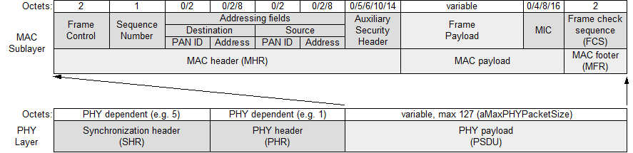
Figure 1. General PHY and MAC frame format.
The general frame formats for PHY and MAC layers were presented in figure 1. The total length of the MAC protocol data unit (MPDU) can not exceed 127 octets (aMaxPHYPacketSize). This value determines the maximum length of a MAC service data unit (MSDU), which can be used by upper layers. The longest MSDU can be obtained by using short addresses within a single cluster and no data protection in the MAC layer. In this case, 116 octets are available for subsequent layers (127-2-1-0-2-2-2-0-0-2). In the opposite situation with full addressing, communication between The general frame formats for PHY and MAC layers were presented in figure 1. The total length of the MAC protocol data unit (MPDU) can not exceed 127 octets (aMaxPHYPacketSize). This value determines the maximum length of a MAC service data unit (MSDU), which can be used by upper layers. The longest MSDU can be obtained by using short addresses within a single cluster and no data protection in the MAC layer. In this case, 116 octets are available for subsequent layers (127-2-1-0-2-2-2-0-0-2). In the opposite situation with full addressing, communication between different clusters and provided data security, we assure only 72 octets for the subsequent layers (127-2-1-2-8-2-8-14-16-2). The PAN cluster can work in one of two modes: beacon-enabled and nonbeacon-enabled.
In the beacon-enabled mode, coordinators periodically emit beacon frames. The time between beacons is organized in a structure called a superframe, see figure 2. The superframe consists of an active and an optional inactive portion. The active part is divided into 16 slots of equal duration. During the inactive part, the coordinator is able to enter a low-power mode without waiting for transmission at that time (turned off transceiver). Beacon frames are used to synchronize associated devices and to transmit the network configuration information. It is possible to specify the time interval between beacons (beacon interval (BI)) and the duration of an active portion (superframe duration (SD)). The active part consists of a contention access period (CAP), where the devices can communicate using slotted CSMA/CA and optionally from the contention-free period (CFP) occurring after CAP. Within the CFP, the PAN coordinator can create guaranteed time slots (GTS), which are the fragments dedicated for low-latency applications or applications requiring specific data bandwidth. The devices granted to use GTS do not have to compete for slots.

Figure 2. Superframe structure.
The IEEE 802.15.4 provides the ability to secure data on the MAC sublayer. The security mechanism provides particular combinations of the following security services: data confidentiality, data authenticity, replay protection. The standard allows all types of frames to be protected except the acknowledgement ones. The specification defines three protection modes: CTR, CBC-MAC, CCM.
The AES-CTR mode ensures only data confidentiality by using the AES block cipher with counter mode, see figure 3.
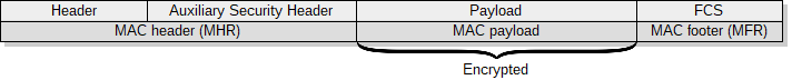
Figure 3. The AES-CTR mode.
The CBC-MAC mode ensures integrity and authenticity of the data and allows for replay protection. A sender computes a message integrity code (MIC) of 4, 8, or 16 bytes in length. Both the header and the payload of L2 are secured, see figure 4.

Figure 4. The CBC-MAC mode.
The CCM mode provides confidentiality as well as integrity and authenticity of data. This mode provides also replay protection. It is implemented by performing CBC-MAC, then performing CTR on the resulting MIC and the payload.

Figure 5. The CCM mode.
2.2 6LoWPAN standard
6LoWPAN is an open standard defined in RFC 49444 by the Internet Engineering Task Force (IETF), a standardization organization that defines many open standards commonly used on the Internet, such as UDP, TCP, HTTP. The standard enables efficient use of IPv6 in low-rate and low power consumption wireless networks through the use of an adaptation layer and optimization of appropriate protocols. Figure 6 shows the location of the adaptation layer in the simplified OSI model. 6LoWPAN is a solution to many of the problems that are present in the IoT concept, e.g.: physical objects require communication with the Internet and services in it, communication between heterogeneous networks is crucial, the ability to communicate both vertically and horizontally is desirable7,8. Using IPv6 to communicate with all physical objects in the IoT concept is a solution to the presented problems, but not directly applicable in IEEE 802.15.4 networks and other networks where frames are short. The IEEE 802.15.4 standard in the worst case leaves 72 octets in a frame for the network layer. The IPv6 packet header has a minimum size of 40 octets and transport layer headers are 8 bytes for UDP and 20 bytes for TCP. Additionally, IPv6 defines the shortest maximum transmission unit (MTU) as 1280 bytes, which requires the use of multiple frames to transmit a single packet. The 6LoWPAN defines an adaptation layer that performs three basic functions: header compression, fragmentation, and L2 forwarding. Headers are nested in the order shown in the figure 7 and are responsible for implementing these functions. The Mesh addressing header is responsible for the L2 forwarding implementation and is skipped if a single hop is used for communication. The fragment header is responsible for packet fragmentation and is elided for packets that fit into one single IEEE 802.15.4 frame. The header format is defined by the header type field (dispatch byte) placed at the beginning of each header. Only a few symbols from dispatch byte are used to represent current LoWPAN functionality and there is still free space for coding additional features in the future to achieve further savings.
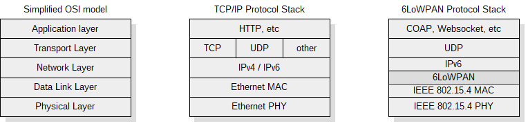
Figure 6. The 6LoWPAN stack in simplified OSI model.

Figure 7. Nested headers in the 6LoWPAN.
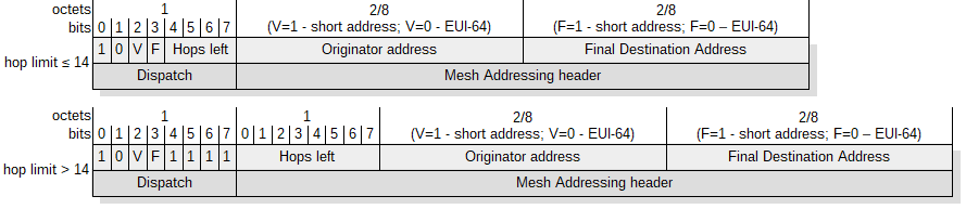 Figure 8. The mesh addressing header structure.
WPAN networks require multi-hop packet forwarding technology to cover a broad area. The IEEE 802.15.4 does not define routing on the data link layer (L2), therefore subsequent layers must take over this role. The adaptation layer defined in the 6LoWPAN between the L2 and the L3 allows the routing mechanism to be placed both under L3 (mesh-under) and at the L3 (route-over) layer. When using mesh-under, a node that does not have direct connection to the destination node places the mesh addressing header with the structure shown in figure 8. At each subsequent hop, the addresses in the L2 header are rewritten to the next node on the path and the hop limit is reduced by 1. It is worth noting that the same functionality could be achieved with the corresponding IPv6 header fields, where the same information can be stored. Unfortunately, such a solution will be problematic in the case of packet fragmentation, when further fragments will reach an intermediary node before the first one. The node will be forced to wait for the first fragment, because only there is an IPv6 packet header indicating the destination address. This approach would create additional latencies in the network as well as require more memory resources.
Packet fragmentation is a necessary step for transmitting IPv6 packet due to the MTU. Each packet that does not fit into the frame is segmented. The structure of fragment header for the first and subsequent fragments is presented in figure 9. A datagram offset defines the place of the fragment in the datagram. The length of the fragment must be a multiple of 8 because 11 bits were reserved for datagram size and only 8 bits for datagram offset. Using mesh-under forwarding assumes the ability of segments to reach the target node in a random order. The standard provides the datagram size in the header for each fragment so that the recipient could reserve a buffer for the whole packet irrespective of the order in which the fragments are received.
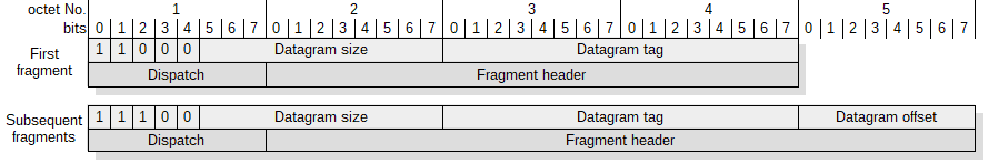
Figure 9. The structure of the first and subsequent fragment headers.
The header compression is the second element needed to place an IPv6 packet on IEEE 802.15.4 layers. The IPv6 packet header has a minimum size of 40 octets and the UDP header is 8 bytes in length. Using uncompressed headers would leave only 24 bytes (72B-48B) as a payload at the transportation layer. There are many compression standards: Van Jacobson TCP / IP Header Compression [RFC 1144], Enhanced Compressed RTP (RTP) [RFC 3545] or Robust Header Compression [RFC 3095]. These standards focus on packet stream compression, assuming that one can extract a specific state and track only its changes. Packet loss is a big problem for these methods, and high compression ratio can only be achieved for longer data streams. 6LoWPAN originally proposed the use of stateless compression, which eliminates the necessity to synchronize state and significantly simplifies the algorithm. In its first release, 6LoWPAN defines two header compression methods: HC1 for IPv6 and HC2 for UDP. Unfortunately, compression of full IPv6 addresses (80% of the header are the addresses) is not possible with stateless compression. Acceptable compression results are only for non-routed link-local addresses where the IPv6/UDP header is compressed down to 7 bytes. The case where both addresses are link-local is very special and in most cases, communication is held from the WPAN to the Internet and vice versa. Compressed headers have up to 31 bytes if global addresses are used. The currently valid compression formats in the 6LoWPAN protocol are IPHC and NHC which are based on contextual compression9. Compression assumes that the nodes attached to the cluster share the same additional context. The IPv6/UDP header can be compressed down to 6 bytes with optimal configuration where link-local addresses are used. Additionally, it is possible to elide the UDP checksum (2 bytes) if there are mechanisms for verifying the integrity of datagram at the lower layers. When security mode that ensures integrity and authenticity of the data is used at MAC layer, the verification is possible by checking the MIC field.
3.Model description
A simulation model was created to determine the transmission overhead in the 6LoWPAN stack. The model allows us to determine the overhead independently for each layer of the stack. The overhead can be calculated for different L4 payload lengths. Created model permits calculations for various sets of options on both MAC sub-layer and adaptation layer of 6LoWPAN standard. Sets of various options were presented in table 1 (section 4).
The transmission overhead strongly depends on the payload length, therefore we propose a method to calculate mean transmission overhead based on the packet length distribution in the Internet. The mean transmission overhead can be used to compare various sets of options. To determine the mean transmission overhead we use two functions defined in 10,11 that were created to model packet length distribution on the Internet. The one of these functions is based on Normal distribution (equation (5) in 10) and the other is based on Beta distribution (equation (11) in 11). In both cases we used functions differently than was originally proposed. The functions were normalized (1) to create probability mass functions for discrete distribution. This approach assures smoother cumulative distribution function (CDF) for very small and high payload sizes, see figure 10. The probability calculated using the original approach11 equals to 0.5 for the payload of 1 B in length, which means that calculated value would be dominated by the overhead of the extremely short payloads (1-2B).
Assuming, that p(l/M) is defined by one of related functions we derive the probability mass function as:
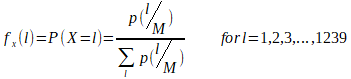
where l is a payload length in bytes and M=1280B is the smallest maximum transmission unit (MTU).


Figure 10. Probability mass functions based on Normal and Beta distribution models (left) and related cumulative distribution functions (right).
The mean transmission overhead can be expressed as an expected value of a discrete random variable (X) for given probability mass function:
![]()
where Ovl is an overhead calculated for packet with L4 payload of length l.
4.Results
Taking into account the large number of possible stack configuration options it is important to use them appropriately. An overhead that comes from L2-L4 headers is a meaningful problem in 6LoWPAN networks. The total size of headers depending on configuration options can be from 17B to more than 100B. Assuming that the payload length on the L1 is constant and equal to 127B the overhead is a significant part of the whole frame. The 6LoWAPN typical header configurations are presented in table 1. Options that have influence on communication overhead are grouped according to layers: PHY, MAC, 6LoWPAN. The overhead is calculated separately for each layer of the stack. The “<L3” column contains the overhead from mesh and fragment headers. This overhead cannot be included either in L2 or L3 layers.
The IEEE 802.15.4 provides identification using both EUI-64 identifiers and short address formats. These 16-bit addresses are dynamically assigned during the bootstrapping of the network. According to the IEEE 802.15.4 specification either the source or destination addresses can be completely elided. However, 6LoWPAN requires that both source and destination addresses are included in the MAC header. In practical applications we can assume that both addresses on MAC layer are always in short form. IEEE 802.15.4 extends both the source and the destination address by a 16-bit PAN identifier each. However, RPL12 which is a prevailing routing protocol for 6LoWPAN standard, provides communication with another PAN using Border Router (LBR). Hence, in practical applications source and destination
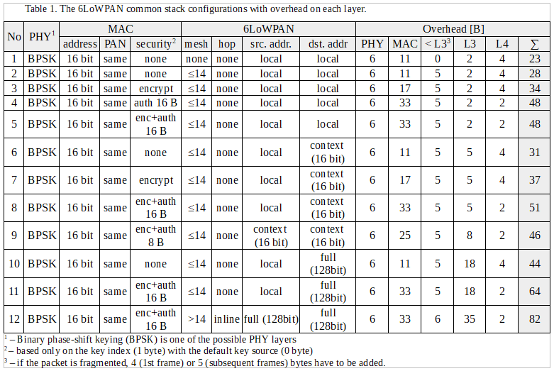
PAN IDs are the same so one can be elided. In consequence, we can assume that on the MAC layer only security settings are variable. The performance impact of different IEEE 802.15.4 security modes was broadly discussed in literature 13. In the analysis we limit ourselves to the case in which the key is identified in the least demanding manner as 1 byte key index with default key source.
One of the 6LoWAPN adaptation layer options that has a significant effect on overhead is the way the frames are forwarded and routed. Both processes can be performed at layer 2 or at layer 3. When routing and forwarding happen at L2 layer (mesh‑under) additional 5-6 bytes are consumed for mesh header (column ”<L3”). Both approaches have advantages and drawbacks which were discussed in 14,15. The second most important option that affects the overhead is how to place IPv6 addresses in the compressed header. The IPv6 addresses can be elided in header if they are link-local addresses formed from interface identifier. In most cases, communication is from or to the Internet. Therefore, at least one address has a global scope. The worst case where both addresses are presented in full form requires as much as 32 bytes in the header. Practical applications mostly seek to use 16 bit addresses that are translated into full IPv6 addresses in the LBR at the point of contact with the Internet. One solution to this is to use contextual compression 9. Unfortunately, there are no widely accepted standards for exchanging information about a shared context within a network16. Additionally, other solutions presented in the literature are also noteworthy17.
The transmission overhead ratio for given datagram payload length (l) can be expressed as:

where F is the number of frames needed to send IP packet with the given payload length at L4, Ov,L1,i, Ov,L2,i, Ov,<L3,i are overheads for subsequent frames at layers L1,L2,<L3, respectively and Ov,L3, Ov,L4 are overheads at layers L3 and L4, respectively.
The transmission overhead ratio strongly depends on the length of the payload. According to the equation 3, headers sent in each frame (L1, L2, <L3) have a greater influence on the overhead ratio than headers sent only in the frame with the first fragment (L3, L4). Assuming O2 = Ov,L3+Ov,L2, O1 = Ov,L1+Ov,L2+Ov,
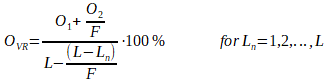
where L is a frame length, F is a number of fragments and Ln is the length of the last frame.
The influence of the overhead from the L3 and L4 headers decreases with the increase in the number of fragments required to transmit the IP packet, see figure 12. It is also worth noting that ripples caused by the fragmentation process decrease as the number of IP packet fragments increases. The overhead on L3 and L4 layers have the greatest impact on packets consisting of a few fragments. Therefore, we can minimize the overhead ratio either by decreasing an overhead or by increasing the frame length.


Figure 11. The overhead ratio versus payload at L4 layer for different security modes (table 1 – options 6,7,8).


Figure 12. The overhead ratio versus payload at L4 layer for different address modes (table 1 – options 9).
Assuming, single frame and single hop basis we can specify the probability of successful frame delivery as:
![]()
where Ptr is the probability to enter transmission stage described in 15, Pcol is a collision probability of performing clear channel assessment (CCA) concurrently described in 18, L is the frame length in bytes and BER is the bit error ratio.
The goodput can be derived as:
![]()
where T is a throughput given for particular PHY and Ov is a transmission overhead.
Assuming Ptr=1 and Pcol=0, we can derive goodput versus frame length for different BER values.


Figure 13. Goodput vs frame length for different BER ratios related to: 23B overhead (left) and 69B overhead (right).
Therefore, taking the frame length and the overhead at the maximum goodput we can plot figure 14.
 Figure 14. The frame length vs total overhead at maximum goodput for different BER ratios.
Goodput depends strongly on the number of nodes competing in getting the channel, as shown in18,15.
The mean transmission overhead was calculated for different frame lengths and specific stack options, see table 2. Two models were used: one based on Normal and the other based on Beta distribution. The data from table 2 are presented in figures 15 and 16.


Figure 15. The mean transmission overhead vs frame length for different security modes calculated using model based on: normal distribution (left), beta distribution (right).


Figure 16. The mean transmission overhead vs frame length for different address modes calculated using model based on: normal distribution (left), beta distribution (right).
5.Conclusions
Optimal use of limited resources and energy efficiency are important issues in LR-WPAN networks. The practical proliferation of IoT requires the use of Internet protocols such as IPv6. Unfortunately, IPv6 is not suitable for efficient use on lossy LR-WPAN networks. The overhead of IPv6 packet delivery in LR-WPAN networks is high and leads to inefficient use of resources. The 6LoWPAN standard defines an adaptation layer to allow use of IPv6 on lossy LR-WPAN networks. The transmission overhead related to L1, L2 and <L3 layers is crucial for optimizing communication efficiency. The overhead related to L3 and L4 layers is only relevant while sending short packets.
The method of calculating the mean transmission overhead was proposed to compare the influence of certain stack options. The mean transmission overhead can be used to optimize the impact of parameters on energy consumption as well as to analyse network behaviour in practical applications. The model based on Beta distribution emphasises the influence of very short packets as well as packets with a length close to the maximum transmission unit (MTU). This model may be more appropriate for practical applications. The calculated mean transmission overhead for using IEEE 802.15.4 compliant frame varies between 40-50% for typical configurations.
The transmission overhead ratio has a significant impact on the goodput (throughput at the application level). To maximize the goodput we minimize the overhead that comes from headers of each layer. Nevertheless, certain header information are required and it is unlikely to get further reduction of headers length. On the other hand, the length of the frame can be extended to maximize the goodput. When the frame is extended by 64 B, the mean transmission overhead is reduced by 11% to 16%, depending on the stack configuration. Goodput can be maximized for longer frames, especially for higher overheads. Taking into account BER, we can increase goodput (transmission efficiency) by extending the frame length for low BERs only. A frame extension at constant BER increases the goodput more for configurations where the overhead ratio is higher. The lossy LR-WPAN networks are characterized by a high fluctuation of BER, hence nodes can work both at small and high BERs. Therefore, it is reasonable to consider an adaptive model that adjusts the frame length to the quality of the transmission channel. The simplest model could extend the frame for N consecutive correct deliveries and shorten to the default length in case of retry.
References
[1] Minerva, R., Biru, A.., Rotondi, D., “Towards a definition of the Internet of Things (IoT),” 1–86 (2015).
[2] Borgia, E., “The internet of things vision: Key features, applications and open issues,” Comput. Commun. 54, 1–31, Elsevier B.V. (2014).
[3] Heile, R. F., “IEEE Standard for Local and metropolitan area networks; Part 15.4: Low-Rate Wireless Personal Area Networks ( LR-WPANs ),” IEEE Computer Society (2011).
[4] Kushalnagar, N., Montenegro, G., Culler, D. E.., Hui, J. W., “Transmission of IPv6 Packets over IEEE 802.15.4 Networks [RFC4944]” (2007).
[5] Chauvenet, C., Tourancheau, B., Genon-Catalot, D., Goudet, P.-E.., Pouillot, M., “A Communication Stack over PLC for Multi Physical Layer IPv6 Networking,” Smart Grid Commun. (SmartGridComm), 2010 First IEEE Int. Conf., 0–5 (2010).
[6] “Guidelines for 64-bit global identifier (EUI-64).”, IEEE Standards Association (2007).
[7] Al-Fuqaha, A., Guizani, M., Mohammadi, M., Aledhari, M.., Ayyash, M., “Internet of Things: A Survey on Enabling Technologies, Protocols, and Applications,” IEEE Commun. Surv. Tutorials 17(4) (2015).
[8] Al-Fuqaha, A., Khreishah, A., Guizani, M., Rayes, A.., Mohammadi, M., “Toward better horizontal integration among IoT services,” IEEE Commun. Mag. 53(9), 72–79 (2015).
[9] Thubert, P.., Hui, J. W., “Compression Format for IPv6 Datagrams in Low Power and Lossy Networks (6LoWPAN) [RFC6282],” 24 (2011).
[10] Castro, E., Kumar, A., Alencar, M. S.., Fonseca, I. E., “A Packet Distribution Traffic Model for Computer Networks,” Proc. Int. Telecommun. Symp., 2–6 (2010).
[11] Castro, E., Alencar, M.., Iguatemi, F., “Probability density functions of the packet length for computer networks with bimodal traffic,” Int. J. Comput. Networks Commun. 5(3) (2013).
[12] Winter, T., “RPL: IPv6 Routing Protocol for Low-Power and Lossy Networks [RFC6550],” Internet Engineering Task Force (IETF) (2012).
[13] Daidone, R., Dini, G.., Anastasi, G., “On evaluating the performance impact of the IEEE 802.15.4 security sub-layer,” Comput. Commun. 47(April 2015), 65–76, Elsevier B.V. (2014).
[14] Chowdhury, A. H., Ikram, M., Cha, H.-S., Redwan, H., Shams, S. M. S., Kim, K.-H.., Yoo, S.-W., “Route-over vs mesh-under routing in 6LoWPAN,” Proc. 2009 Int. Conf. Wirel. Commun. Mob. Comput. Connect. World Wirelessly – IWCMC ’09, 1208 (2009).
[15] Lee, T.-H., Chu, H.-C., Chang, L.-H., Chiang, H.-S.., Lin, Y.-W., “Modeling and Performance Analysis of Route-Over and Mesh-Under Routing Schemes in 6LoWPAN under Error-Prone Channel Condition,” J. Appl. Math. 2013, 1–9 (2013).
[16] Li, N.., Huang, X., “A context system for 6LoWPAN network,” Proc. – 2011 4th IEEE Int. Conf. Broadband Netw. Multimed. Technol. IC-BNMT 2011, 522–525 (2011).
[17] Publishing, I., Ma, L., Wang, G., Ma, D.., He, J., “IP communication optimization for 6LoWPAN-Based Wireless Sensor Networks,” Sensors & Transducers 174(7), 81–87 (2014).
[18] Zhang, Y.., Shu, F., “Packet size optimization for goodput and energy efficiency enhancement in slotted IEEE 802.15.4 networks,” IEEE Wirel. Commun. Netw. Conf. WCNC (2009).
Analysing efficiency of IPv6 packet transmission
over 6LoWPAN network
autorzy:
Adam Kozłowskia, Janusz Sosnowskia
(aInstitute of Computer Science, Warsaw University of Technology, ul. Nowowiejska 15/18, Warsaw 00-665, Poland)
Abstract
Practical proliferation of Internet of Things (IoT) concept depends upon communication efficiency in the related network. In the paper we outline basic features of wireless communication protocols used in IoT and concentrate on analysing communication overheads. In particular, we discuss the impact of IPv6 packet length on 6LoWPAN network operation with physical and MAC layer defined by IEEE 802.15.4 standard. The presented analysis methodology is useful in estimation of the total goodput (throughput at the application level) and energy consumptions within the whole traffic model which are the crucial features of IoT networks.
Keywords
Personal area network, IoT, transmission overhead, 6LoWPAN, IEEE 802.15.4
1 Introduction
The Internet of things (IoT) concept covers several areas such as: communication, embedded computing, cloud computing and others. There are plenty of definitions of the IoT1 but in most of them we can distinguish the main idea which is network of uniquely identifiable physical objects interoperating within the existing Internet infrastructure. According to this definition we can find IP protocol suite to be inherent in the IoT concept. There are prognoses that the IoT will consist of more than 7 trillion objects by 20252, with an estimate of about 1000 devices per person. IPv6 protocol has enough address space to meet even further proliferation hence it is a reasonable and natural choice for the IoT. The use of an end-to-end, IP-based infrastructure takes full advantage of 40+ years of IP technology development. Wireless communication is another intrinsic feature of the IoT paradigm. There are many groups of physical objects where wireless transmission is the only feasible solution. The IEEE 802 Standard Committee develops and maintains networking standards and recommended practices. Standards for connecting physical objects with limited computing or memory resources and working without external energy for years play a special role in the development of the IoT. In particular, IEEE 802.15.4 standard3 addressed for low-cost and low-bandwidth connections provides the capability of energy consumption reduction. The use of IP protocol in low-power, wireless personal area networks (LoWPANs) was not considered for a long time because these networks are highly constrained and must operate unattended on batteries for years. Additionally, IPv6 increases the smallest (within transmission paths) maximum transmission unit (MTU) from 576 B to 1280 B. The payload of the physical frame in the IEEE 802.15.4 can be up to 127 bytes in size, with 72‑116 bytes of payload available after link-layer framing, depending on the number of addressing and security options.
6LoWPAN4 is an IETF protocol that allows IPv6 packets to be carried efficiently within small link layer frames, such as those defined by IEEE 802.15.4. The 6LoWPAN introduces an adaptation layer between the IP stack’s link and network layers to enable transmission of IPv6 packets. Transmission of IPv6 packets within small frame (PHY payload – 127 B) leads to significant transmission overhead. The length of a payload at higher layers is relatively short compared to the length of the frame. Overhead that comes from all the layers of stack has meaningful influence on total energy consumption within the entire network. It can be assumed that the energy consumption in a transmission is directly proportional to the number of sent symbols (bytes). Therefore, it is important to maximize the goodput so that less energy is consumed by all the redundant elements e.g. headers, control packets, beacons, etc.
It is crucial to assess the transmission overhead to effectively design and build 6LoWPAN networks. In the paper we analyse the overhead basing on different sets of stack options. There are some options which have meaningful impact and have to be used reasonably, they are discussed in section 2. Section 3 introduces an original model that allows determining the overhead on each layer of the stack. The mean transmission overhead of the 6LoWPAN stack was derived based on different probability distributions of the packet length within the Internet. The results are presented in section 4 followed by conclusions in section 5.
2. The 6LoWPAN stack characterisation
The 6LoWPAN protocol allows for efficient transmission of IPv6 packets over IEEE 802.15.4 networks. The stack has been designed with IEEE 802.15.4 in mind. Concentrating on a specific link-layer technology has allowed 6LoWPAN Working Group to avoid going into complex, hard to implement generalizations. Certain solutions in the 6LoWPAN format specification are closely tied to features of the IEEE 802.15.4 link layer. However, other link-layer technologies are also possible such as Power Line Communication (PLC)5.
2.1 IEEE 802.15.4 standard
The IEEE 802.15.4 standard defines the physical layer (PHY) and medium access control (MAC) sublayer specifications for low-data-rate wireless connectivity (<250 kbit/s) with devices typically operating in the Personal Area Network (LR-WPAN). The IEEE 802 Committee divides the classical OSI data link layer (L2) into two sublayers: Logical Link Control (LLC) and Media Access Control (MAC). The standard in its first IEEE 802.15.4-2003 release defines two types of PHY layers. The latest IEEE 802.15.4-2015 release specifies 19 PHY layers. The standard is actively developed while Working Group constantly releases amendments addressing specific groups of problems e.g. the problem of reducing energy consumption and introducing 2 additional PHY layers in 2016.
Two different device types can participate in IEEE 802.15.4 network: a full-function device (FFD) and a reduced-function device (RFD). The 802.15.4 WPAN cluster consists of two or more devices, where at least one is FFD type and serves as PAN coordinator. An RFD device can not be a coordinator and a PAN coordinator, it only associates with a single FFD at a time. Therefore, RFD can be implemented using minimal resources and memory capacity. Depending on the application requirements, IEEE 802.15.4 LR-WPAN operates in either of two topologies:
• The star topology, where devices can only communicate with a single PAN coordinator;
• The peer-to-peer topology, where any device is able to communicate with any other device as long as they are in the range of one another. A peer-to-peer network allows multiple hops to route messages from any device to any other device in the network. This configuration allows to implement more complex networks e.g. mesh topology.
Each device requires a 64-bit Extended Unique Identifier (EUI-64)6. The PAN coordinator selects a unique 16-bit identifier common to the entire PAN cluster. The PAN identifier allows the cluster to use the shortened 16-bit address format. The standard defines four types of frames in the MAC sublayer: beacon frame (used by the coordinator to send network configuration information and device synchronization), data frame, acknowledgement frame and MAC command frame.
Figure 1. General PHY and MAC frame format.
The general frame formats for PHY and MAC layers were presented in figure 1. The total length of the MAC protocol data unit (MPDU) can not exceed 127 octets (aMaxPHYPacketSize). This value determines the maximum length of a MAC service data unit (MSDU), which can be used by upper layers. The longest MSDU can be obtained by using short addresses within a single cluster and no data protection in the MAC layer. In this case, 116 octets are available for subsequent layers (127-2-1-0-2-2-2-0-0-2). In the opposite situation with full addressing, communication between The general frame formats for PHY and MAC layers were presented in figure 1. The total length of the MAC protocol data unit (MPDU) can not exceed 127 octets (aMaxPHYPacketSize). This value determines the maximum length of a MAC service data unit (MSDU), which can be used by upper layers. The longest MSDU can be obtained by using short addresses within a single cluster and no data protection in the MAC layer. In this case, 116 octets are available for subsequent layers (127-2-1-0-2-2-2-0-0-2). In the opposite situation with full addressing, communication between different clusters and provided data security, we assure only 72 octets for the subsequent layers (127-2-1-2-8-2-8-14-16-2). The PAN cluster can work in one of two modes: beacon-enabled and nonbeacon-enabled.
In the beacon-enabled mode, coordinators periodically emit beacon frames. The time between beacons is organized in a structure called a superframe, see figure 2. The superframe consists of an active and an optional inactive portion. The active part is divided into 16 slots of equal duration. During the inactive part, the coordinator is able to enter a low-power mode without waiting for transmission at that time (turned off transceiver). Beacon frames are used to synchronize associated devices and to transmit the network configuration information. It is possible to specify the time interval between beacons (beacon interval (BI)) and the duration of an active portion (superframe duration (SD)). The active part consists of a contention access period (CAP), where the devices can communicate using slotted CSMA/CA and optionally from the contention-free period (CFP) occurring after CAP. Within the CFP, the PAN coordinator can create guaranteed time slots (GTS), which are the fragments dedicated for low-latency applications or applications requiring specific data bandwidth. The devices granted to use GTS do not have to compete for slots.
Figure 2. Superframe structure.
The IEEE 802.15.4 provides the ability to secure data on the MAC sublayer. The security mechanism provides particular combinations of the following security services: data confidentiality, data authenticity, replay protection. The standard allows all types of frames to be protected except the acknowledgement ones. The specification defines three protection modes: CTR, CBC-MAC, CCM.
The AES-CTR mode ensures only data confidentiality by using the AES block cipher with counter mode, see figure 3.
Figure 3. The AES-CTR mode.
The CBC-MAC mode ensures integrity and authenticity of the data and allows for replay protection. A sender computes a message integrity code (MIC) of 4, 8, or 16 bytes in length. Both the header and the payload of L2 are secured, see figure 4.
Figure 4. The CBC-MAC mode.
The CCM mode provides confidentiality as well as integrity and authenticity of data. This mode provides also replay protection. It is implemented by performing CBC-MAC, then performing CTR on the resulting MIC and the payload.
Figure 5. The CCM mode.
2.2 6LoWPAN standard
6LoWPAN is an open standard defined in RFC 49444 by the Internet Engineering Task Force (IETF), a standardization organization that defines many open standards commonly used on the Internet, such as UDP, TCP, HTTP. The standard enables efficient use of IPv6 in low-rate and low power consumption wireless networks through the use of an adaptation layer and optimization of appropriate protocols. Figure 6 shows the location of the adaptation layer in the simplified OSI model. 6LoWPAN is a solution to many of the problems that are present in the IoT concept, e.g.: physical objects require communication with the Internet and services in it, communication between heterogeneous networks is crucial, the ability to communicate both vertically and horizontally is desirable7,8. Using IPv6 to communicate with all physical objects in the IoT concept is a solution to the presented problems, but not directly applicable in IEEE 802.15.4 networks and other networks where frames are short. The IEEE 802.15.4 standard in the worst case leaves 72 octets in a frame for the network layer. The IPv6 packet header has a minimum size of 40 octets and transport layer headers are 8 bytes for UDP and 20 bytes for TCP. Additionally, IPv6 defines the shortest maximum transmission unit (MTU) as 1280 bytes, which requires the use of multiple frames to transmit a single packet. The 6LoWPAN defines an adaptation layer that performs three basic functions: header compression, fragmentation, and L2 forwarding. Headers are nested in the order shown in the figure 7 and are responsible for implementing these functions. The Mesh addressing header is responsible for the L2 forwarding implementation and is skipped if a single hop is used for communication. The fragment header is responsible for packet fragmentation and is elided for packets that fit into one single IEEE 802.15.4 frame. The header format is defined by the header type field (dispatch byte) placed at the beginning of each header. Only a few symbols from dispatch byte are used to represent current LoWPAN functionality and there is still free space for coding additional features in the future to achieve further savings.
Figure 6. The 6LoWPAN stack in simplified OSI model.
Figure 7. Nested headers in the 6LoWPAN.
Figure 8. The mesh addressing header structure.
WPAN networks require multi-hop packet forwarding technology to cover a broad area. The IEEE 802.15.4 does not define routing on the data link layer (L2), therefore subsequent layers must take over this role. The adaptation layer defined in the 6LoWPAN between the L2 and the L3 allows the routing mechanism to be placed both under L3 (mesh-under) and at the L3 (route-over) layer. When using mesh-under, a node that does not have direct connection to the destination node places the mesh addressing header with the structure shown in figure 8. At each subsequent hop, the addresses in the L2 header are rewritten to the next node on the path and the hop limit is reduced by 1. It is worth noting that the same functionality could be achieved with the corresponding IPv6 header fields, where the same information can be stored. Unfortunately, such a solution will be problematic in the case of packet fragmentation, when further fragments will reach an intermediary node before the first one. The node will be forced to wait for the first fragment, because only there is an IPv6 packet header indicating the destination address. This approach would create additional latencies in the network as well as require more memory resources.
Packet fragmentation is a necessary step for transmitting IPv6 packet due to the MTU. Each packet that does not fit into the frame is segmented. The structure of fragment header for the first and subsequent fragments is presented in figure 9. A datagram offset defines the place of the fragment in the datagram. The length of the fragment must be a multiple of 8 because 11 bits were reserved for datagram size and only 8 bits for datagram offset. Using mesh-under forwarding assumes the ability of segments to reach the target node in a random order. The standard provides the datagram size in the header for each fragment so that the recipient could reserve a buffer for the whole packet irrespective of the order in which the fragments are received.
Figure 9. The structure of the first and subsequent fragment headers.
The header compression is the second element needed to place an IPv6 packet on IEEE 802.15.4 layers. The IPv6 packet header has a minimum size of 40 octets and the UDP header is 8 bytes in length. Using uncompressed headers would leave only 24 bytes (72B-48B) as a payload at the transportation layer. There are many compression standards: Van Jacobson TCP / IP Header Compression [RFC 1144], Enhanced Compressed RTP (RTP) [RFC 3545] or Robust Header Compression [RFC 3095]. These standards focus on packet stream compression, assuming that one can extract a specific state and track only its changes. Packet loss is a big problem for these methods, and high compression ratio can only be achieved for longer data streams. 6LoWPAN originally proposed the use of stateless compression, which eliminates the necessity to synchronize state and significantly simplifies the algorithm. In its first release, 6LoWPAN defines two header compression methods: HC1 for IPv6 and HC2 for UDP. Unfortunately, compression of full IPv6 addresses (80% of the header are the addresses) is not possible with stateless compression. Acceptable compression results are only for non-routed link-local addresses where the IPv6/UDP header is compressed down to 7 bytes. The case where both addresses are link-local is very special and in most cases, communication is held from the WPAN to the Internet and vice versa. Compressed headers have up to 31 bytes if global addresses are used. The currently valid compression formats in the 6LoWPAN protocol are IPHC and NHC which are based on contextual compression9. Compression assumes that the nodes attached to the cluster share the same additional context. The IPv6/UDP header can be compressed down to 6 bytes with optimal configuration where link-local addresses are used. Additionally, it is possible to elide the UDP checksum (2 bytes) if there are mechanisms for verifying the integrity of datagram at the lower layers. When security mode that ensures integrity and authenticity of the data is used at MAC layer, the verification is possible by checking the MIC field.
3.Model description
A simulation model was created to determine the transmission overhead in the 6LoWPAN stack. The model allows us to determine the overhead independently for each layer of the stack. The overhead can be calculated for different L4 payload lengths. Created model permits calculations for various sets of options on both MAC sub-layer and adaptation layer of 6LoWPAN standard. Sets of various options were presented in table 1 (section 4).
The transmission overhead strongly depends on the payload length, therefore we propose a method to calculate mean transmission overhead based on the packet length distribution in the Internet. The mean transmission overhead can be used to compare various sets of options. To determine the mean transmission overhead we use two functions defined in 10,11 that were created to model packet length distribution on the Internet. The one of these functions is based on Normal distribution (equation (5) in 10) and the other is based on Beta distribution (equation (11) in 11). In both cases we used functions differently than was originally proposed. The functions were normalized (1) to create probability mass functions for discrete distribution. This approach assures smoother cumulative distribution function (CDF) for very small and high payload sizes, see figure 10. The probability calculated using the original approach11 equals to 0.5 for the payload of 1 B in length, which means that calculated value would be dominated by the overhead of the extremely short payloads (1-2B).
Assuming, that p(l/M) is defined by one of related functions we derive the probability mass function as:
where l is a payload length in bytes and M=1280B is the smallest maximum transmission unit (MTU).
Figure 10. Probability mass functions based on Normal and Beta distribution models (left) and related cumulative distribution functions (right).
The mean transmission overhead can be expressed as an expected value of a discrete random variable (X) for given probability mass function:
![]()
where Ovl is an overhead calculated for packet with L4 payload of length l.
4.Results
Taking into account the large number of possible stack configuration options it is important to use them appropriately. An overhead that comes from L2-L4 headers is a meaningful problem in 6LoWPAN networks. The total size of headers depending on configuration options can be from 17B to more than 100B. Assuming that the payload length on the L1 is constant and equal to 127B the overhead is a significant part of the whole frame. The 6LoWAPN typical header configurations are presented in table 1. Options that have influence on communication overhead are grouped according to layers: PHY, MAC, 6LoWPAN. The overhead is calculated separately for each layer of the stack. The “<L3” column contains the overhead from mesh and fragment headers. This overhead cannot be included either in L2 or L3 layers.
The IEEE 802.15.4 provides identification using both EUI-64 identifiers and short address formats. These 16-bit addresses are dynamically assigned during the bootstrapping of the network. According to the IEEE 802.15.4 specification either the source or destination addresses can be completely elided. However, 6LoWPAN requires that both source and destination addresses are included in the MAC header. In practical applications we can assume that both addresses on MAC layer are always in short form. IEEE 802.15.4 extends both the source and the destination address by a 16-bit PAN identifier each. However, RPL12 which is a prevailing routing protocol for 6LoWPAN standard, provides communication with another PAN using Border Router (LBR). Hence, in practical applications source and destination
PAN IDs are the same so one can be elided. In consequence, we can assume that on the MAC layer only security settings are variable. The performance impact of different IEEE 802.15.4 security modes was broadly discussed in literature 13. In the analysis we limit ourselves to the case in which the key is identified in the least demanding manner as 1 byte key index with default key source.
One of the 6LoWAPN adaptation layer options that has a significant effect on overhead is the way the frames are forwarded and routed. Both processes can be performed at layer 2 or at layer 3. When routing and forwarding happen at L2 layer (mesh‑under) additional 5-6 bytes are consumed for mesh header (column ”<L3”). Both approaches have advantages and drawbacks which were discussed in 14,15. The second most important option that affects the overhead is how to place IPv6 addresses in the compressed header. The IPv6 addresses can be elided in header if they are link-local addresses formed from interface identifier. In most cases, communication is from or to the Internet. Therefore, at least one address has a global scope. The worst case where both addresses are presented in full form requires as much as 32 bytes in the header. Practical applications mostly seek to use 16 bit addresses that are translated into full IPv6 addresses in the LBR at the point of contact with the Internet. One solution to this is to use contextual compression 9. Unfortunately, there are no widely accepted standards for exchanging information about a shared context within a network16. Additionally, other solutions presented in the literature are also noteworthy17.
The transmission overhead ratio for given datagram payload length (l) can be expressed as:
where F is the number of frames needed to send IP packet with the given payload length at L4, Ov,L1,i, Ov,L2,i, Ov,<L3,i are overheads for subsequent frames at layers L1,L2,<L3, respectively and Ov,L3, Ov,L4 are overheads at layers L3 and L4, respectively.
The transmission overhead ratio strongly depends on the length of the payload. According to the equation 3, headers sent in each frame (L1, L2, <L3) have a greater influence on the overhead ratio than headers sent only in the frame with the first fragment (L3, L4). Assuming O2 = Ov,L3+Ov,L2, O1 = Ov,L1+Ov,L2+Ov,
where L is a frame length, F is a number of fragments and Ln is the length of the last frame.
The influence of the overhead from the L3 and L4 headers decreases with the increase in the number of fragments required to transmit the IP packet, see figure 12. It is also worth noting that ripples caused by the fragmentation process decrease as the number of IP packet fragments increases. The overhead on L3 and L4 layers have the greatest impact on packets consisting of a few fragments. Therefore, we can minimize the overhead ratio either by decreasing an overhead or by increasing the frame length.
Figure 11. The overhead ratio versus payload at L4 layer for different security modes (table 1 – options 6,7,8).
Figure 12. The overhead ratio versus payload at L4 layer for different address modes (table 1 – options 9).
Assuming, single frame and single hop basis we can specify the probability of successful frame delivery as:
![]()
where Ptr is the probability to enter transmission stage described in 15, Pcol is a collision probability of performing clear channel assessment (CCA) concurrently described in 18, L is the frame length in bytes and BER is the bit error ratio.
The goodput can be derived as:
![]()
where T is a throughput given for particular PHY and Ov is a transmission overhead.
Assuming Ptr=1 and Pcol=0, we can derive goodput versus frame length for different BER values.
Figure 13. Goodput vs frame length for different BER ratios related to: 23B overhead (left) and 69B overhead (right).
Therefore, taking the frame length and the overhead at the maximum goodput we can plot figure 14.
Figure 14. The frame length vs total overhead at maximum goodput for different BER ratios.
Goodput depends strongly on the number of nodes competing in getting the channel, as shown in18,15.
The mean transmission overhead was calculated for different frame lengths and specific stack options, see table 2. Two models were used: one based on Normal and the other based on Beta distribution. The data from table 2 are presented in figures 15 and 16.
Figure 15. The mean transmission overhead vs frame length for different security modes calculated using model based on: normal distribution (left), beta distribution (right).
Figure 16. The mean transmission overhead vs frame length for different address modes calculated using model based on: normal distribution (left), beta distribution (right).
5. Conclusions
Optimal use of limited resources and energy efficiency are important issues in LR-WPAN networks. The practical proliferation of IoT requires the use of Internet protocols such as IPv6. Unfortunately, IPv6 is not suitable for efficient use on lossy LR-WPAN networks. The overhead of IPv6 packet delivery in LR-WPAN networks is high and leads to inefficient use of resources. The 6LoWPAN standard defines an adaptation layer to allow use of IPv6 on lossy LR-WPAN networks. The transmission overhead related to L1, L2 and <L3 layers is crucial for optimizing communication efficiency. The overhead related to L3 and L4 layers is only relevant while sending short packets.
The method of calculating the mean transmission overhead was proposed to compare the influence of certain stack options. The mean transmission overhead can be used to optimize the impact of parameters on energy consumption as well as to analyse network behaviour in practical applications. The model based on Beta distribution emphasises the influence of very short packets as well as packets with a length close to the maximum transmission unit (MTU). This model may be more appropriate for practical applications. The calculated mean transmission overhead for using IEEE 802.15.4 compliant frame varies between 40-50% for typical configurations.
The transmission overhead ratio has a significant impact on the goodput (throughput at the application level). To maximize the goodput we minimize the overhead that comes from headers of each layer. Nevertheless, certain header information are required and it is unlikely to get further reduction of headers length. On the other hand, the length of the frame can be extended to maximize the goodput. When the frame is extended by 64 B, the mean transmission overhead is reduced by 11% to 16%, depending on the stack configuration. Goodput can be maximized for longer frames, especially for higher overheads. Taking into account BER, we can increase goodput (transmission efficiency) by extending the frame length for low BERs only. A frame extension at constant BER increases the goodput more for configurations where the overhead ratio is higher. The lossy LR-WPAN networks are characterized by a high fluctuation of BER, hence nodes can work both at small and high BERs. Therefore, it is reasonable to consider an adaptive model that adjusts the frame length to the quality of the transmission channel. The simplest model could extend the frame for N consecutive correct deliveries and shorten to the default length in case of retry.
References
[1] Minerva, R., Biru, A.., Rotondi, D., “Towards a definition of the Internet of Things (IoT),” 1–86 (2015).
[2] Borgia, E., “The internet of things vision: Key features, applications and open issues,” Comput. Commun. 54, 1–31, Elsevier B.V. (2014).
[3] Heile, R. F., “IEEE Standard for Local and metropolitan area networks; Part 15.4: Low-Rate Wireless Personal Area Networks ( LR-WPANs ),” IEEE Computer Society (2011).
[4] Kushalnagar, N., Montenegro, G., Culler, D. E.., Hui, J. W., “Transmission of IPv6 Packets over IEEE 802.15.4 Networks [RFC4944]” (2007).
[5] Chauvenet, C., Tourancheau, B., Genon-Catalot, D., Goudet, P.-E.., Pouillot, M., “A Communication Stack over PLC for Multi Physical Layer IPv6 Networking,” Smart Grid Commun. (SmartGridComm), 2010 First IEEE Int. Conf., 0–5 (2010).
[6] “Guidelines for 64-bit global identifier (EUI-64).”, IEEE Standards Association (2007).
[7] Al-Fuqaha, A., Guizani, M., Mohammadi, M., Aledhari, M.., Ayyash, M., “Internet of Things: A Survey on Enabling Technologies, Protocols, and Applications,” IEEE Commun. Surv. Tutorials 17(4) (2015).
[8] Al-Fuqaha, A., Khreishah, A., Guizani, M., Rayes, A.., Mohammadi, M., “Toward better horizontal integration among IoT services,” IEEE Commun. Mag. 53(9), 72–79 (2015).
[9] Thubert, P.., Hui, J. W., “Compression Format for IPv6 Datagrams in Low Power and Lossy Networks (6LoWPAN) [RFC6282],” 24 (2011).
[10] Castro, E., Kumar, A., Alencar, M. S.., Fonseca, I. E., “A Packet Distribution Traffic Model for Computer Networks,” Proc. Int. Telecommun. Symp., 2–6 (2010).
[11] Castro, E., Alencar, M.., Iguatemi, F., “Probability density functions of the packet length for computer networks with bimodal traffic,” Int. J. Comput. Networks Commun. 5(3) (2013).
[12] Winter, T., “RPL: IPv6 Routing Protocol for Low-Power and Lossy Networks [RFC6550],” Internet Engineering Task Force (IETF) (2012).
[13] Daidone, R., Dini, G.., Anastasi, G., “On evaluating the performance impact of the IEEE 802.15.4 security sub-layer,” Comput. Commun. 47(April 2015), 65–76, Elsevier B.V. (2014).
[14] Chowdhury, A. H., Ikram, M., Cha, H.-S., Redwan, H., Shams, S. M. S., Kim, K.-H.., Yoo, S.-W., “Route-over vs mesh-under routing in 6LoWPAN,” Proc. 2009 Int. Conf. Wirel. Commun. Mob. Comput. Connect. World Wirelessly – IWCMC ’09, 1208 (2009).
[15] Lee, T.-H., Chu, H.-C., Chang, L.-H., Chiang, H.-S.., Lin, Y.-W., “Modeling and Performance Analysis of Route-Over and Mesh-Under Routing Schemes in 6LoWPAN under Error-Prone Channel Condition,” J. Appl. Math. 2013, 1–9 (2013).
[16] Li, N.., Huang, X., “A context system for 6LoWPAN network,” Proc. – 2011 4th IEEE Int. Conf. Broadband Netw. Multimed. Technol. IC-BNMT 2011, 522–525 (2011).
[17] Publishing, I., Ma, L., Wang, G., Ma, D.., He, J., “IP communication optimization for 6LoWPAN-Based Wireless Sensor Networks,” Sensors & Transducers 174(7), 81–87 (2014).
[18] Zhang, Y.., Shu, F., “Packet size optimization for goodput and energy efficiency enhancement in slotted IEEE 802.15.4 networks,” IEEE Wirel. Commun. Netw. Conf. WCNC (2009).